Description
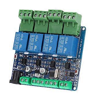
4‑Channel Relay Module 12V High Accuracy Switch Input for RS485/TTL Communication
1、This is a 4‑channel 12V relay output board module. easy and convenient to install 2、High quality material can make sure the durability and stability of the product 3、The module has low power consumption, high accuracy, suitable for RS485 / TTL communication 4、Adopted of high quality electronic components, and accuracy process, ensure for the durability 5、The connecting part has good contact performance, ensure stable working
Item Type: 4-Channel Relay Module
Relay Communication: Multi-unit network 485 communication, the default communication address is 1, and the user can modify the address by himself
Note: IN1-IN4 are used to connect to the switch and read the switch status through 485, not to control the relay output through the input.
The switch status of IN1-IN4 needs to be read by the computer every time it is inquired, and data cannot be sent to 485 actively.
Note: IN1-IN4 cannot be connected to 220V (some buyers will make this mistake)
The Wiring Method is as Follows:
IN1-GND (default is high level, low level after the switch is turned on) The computer sends instructions to read the switch status.
IN2-GND (default is high level, low level after the switch is turned on) the computer sends instructions to read the switch status.
IN3-GND (default is high level, low level after the switch is turned on) the computer sends instructions to read the switch status.
IN4-GND (default is high level, low level after the switch is turned on) the computer sends instructions to read the switch status.
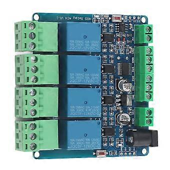
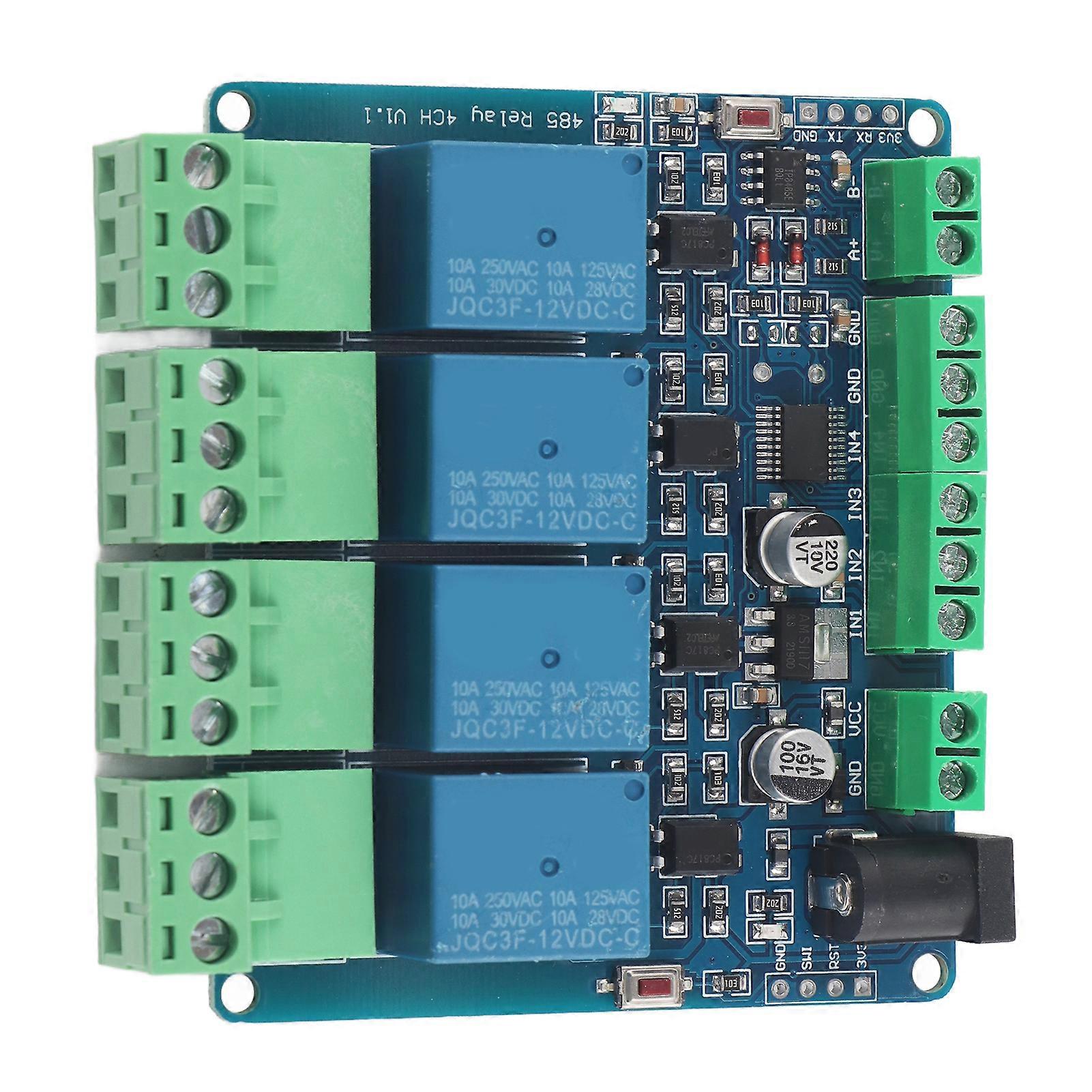
Board Resources:
1. S1 reset button
2. D5 running LED indicator
Control instruction into group sharing download
1. 4 relay outputs (one normally open, one normally closed)
2. STM8S103F3 MCU
3. 4 optocoupler isolation relay output
4. 4 relay closed LED indicators
5. Circular DC interface, and terminal DC interface. Convenient power connection (power supply voltage 5V or 12V depends on the voltage of the relay)
6. 4 input interfaces (dry node input, passive input, connected to GND)
7. One RS485 communication interface.
8. A power indicator
9. One user LED light
10. Reset button
11. A SWIM download interface-(STLINK-V2 download program, users can develop the program twice)
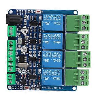
1. Connect LED to user LED
2. TX RX connects to port 485 and pin header TTL port
3. KEY user button (red button on the left)
4. EN 485 use end
5. IN1 -IN4 input ports are directly connected to the terminals
6.K1 -K4 relay output control
7. SWIM programming program J13 Size: Approx. 76 x 67mm / 3 x 2.6in
1 x 4-Channel Relay Module
-
Fruugo ID:
388901835-834014243
-
EAN:
680141788793
Product Safety Information
Please see the product safety information specific to this product outlined below
The following information is provided by the independent third-party retailer selling this product.
Product Safety Labels

Safety Warnings:
-
Not suitable for children under 36 months
-
Choking Hazard
-
Adult supervision recommended
Delivery & Returns
Dispatched within 2 days
Shipping from China.
We do our best to ensure that the products that you order are delivered to you in full and according to your specifications. However, should you receive an incomplete order, or items different from the ones you ordered, or there is some other reason why you are not satisfied with the order, you may return the order, or any products included in the order, and receive a full refund for the items. View full return policy